- Papers on Wireless Power Transfer & Beamforming
- Lectures on Wireless Power Transfer & Beamforming
- Simplified Phased Array Project
Papers on Wireless Power Transfer & Beamforming
Lectures on Wireless Power Transfer & Beamforming
Simplified Phased Array Project
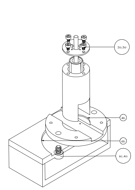
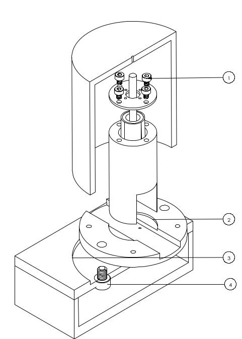
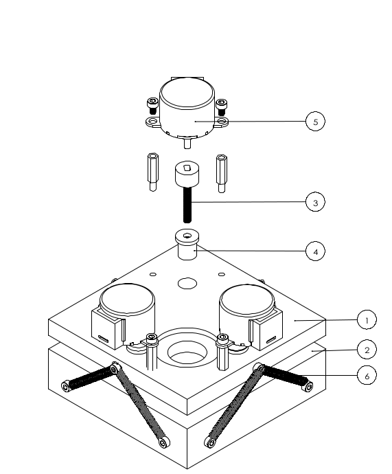
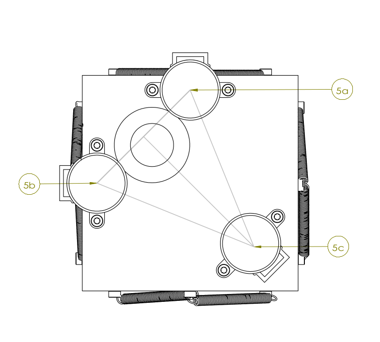
Hardware
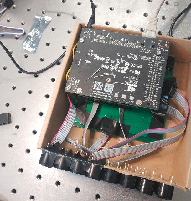
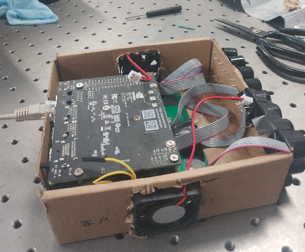
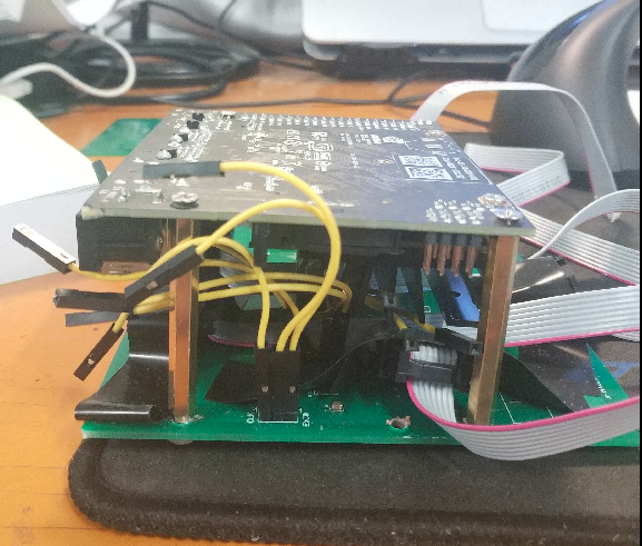
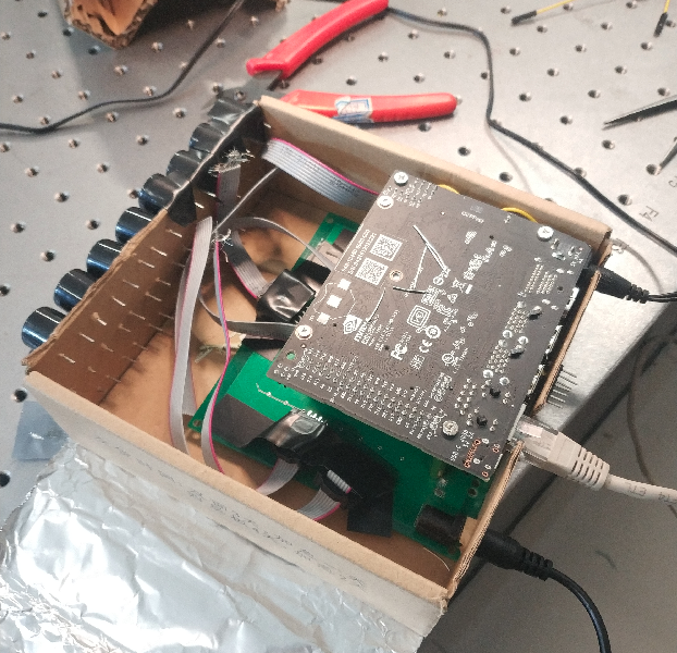
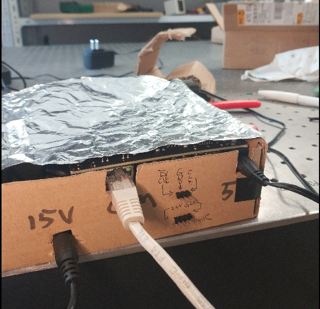
Controller
lecture on microcontroller
controller for phased array
#include "TM4C123GH6PM.h"
#include "Configure.h"
#include <assert.h>
#include <stdint.h>
#include <stdio.h>
#include <stdlib.h>

int main() {
  Init_Board();
  Init_UART1();
  const uint32_t * start = Phased();
    while (1) {
      for(uint32_t i=0;i<2*half_wave;++i){
        GPIOB_AHB->DATA_Bits[0xFF]=*(start+i);
      }
    }
}
#include "TM4C123GH6PM.h"

extern uint32_t phased_array[10];
extern uint32_t * iterators[10];
extern const uint32_t half_wave;
extern const uint32_t number_of_transducers;

const uint32_t * Phased(){
  //setup the basic 3/2 pi wave
  const uint32_t n = 3*half_wave;
  uint32_t * gpio_data = (uint32_t*) malloc(n * sizeof(uint32_t));
  for (uint32_t i = 0; i <3; ++i) {
          gpio_data[i*half_wave] = (i % 2 == 0) ? 1 : 0;
          for (uint32_t j=1; j<half_wave; ++j){

           gpio_data[i*half_wave+j]=gpio_data[i*half_wave];
          }
  }

  const uint32_t phase = 1;

  for (int i=0;i<number_of_transducers;++i){
	  phased_array[i]=i%17;
	 }

  for (int i=0; i<number_of_transducers; ++i){
         iterators[i]=gpio_data+phased_array[i]*phase;
  }

  //the actual phased array wave
   const uint32_t wave_length=2*half_wave;
   uint32_t * st_ptr = (uint32_t*) malloc(wave_length * sizeof(uint32_t));

 //initialize everything to zero
 for(uint32_t i=0;i<wave_length;++i){
	 *(st_ptr+i)=0;
 }
 //put set_mask into the wave
    for (uint32_t j=0; j<number_of_transducers; ++j){
      for(uint32_t i=0;i<wave_length;++i){
          if(*(iterators[j])==1) {
         *(st_ptr+i) = *(st_ptr+i) | (1U << j);
        }
          else{
            *(st_ptr+i) = *(st_ptr+i) & ~ (1U << j);
          }
        ++iterators[j];
       }
    }
 return st_ptr;
}
#include "TM4C123GH6PM.h"
#define XTAL_16MHZ   0x00000540  // 16 MHz Crystal

void Init_Board(){

//SYSCTL->RCC = (1U<<5);//enable internal clock 16MHz
SYSCTL->RCC= SYSCTL->RCC & (~(3U<<4));//use the main oscillator
SYSCTL->RCC= SYSCTL->RCC |  (15U<<6); //set the xtal value to be 16M


/*portB related initialization*/
SYSCTL->RCGCGPIO  = SYSCTL->RCGCGPIO | (1U<<1); //enable GPIO Port B
SYSCTL->GPIOHBCTL = SYSCTL->GPIOHBCTL |(1U<<1); //enable HBC bus for Port B
GPIOB_AHB->DIR = 0xFF; //set direction as output for all pins
GPIOB_AHB->DEN = 0xFF; //enable all pins

/*UART related Initialization*/

SYSCTL->RCGCUART = SYSCTL->RCGCUART | (1U<<1); //enable U1, U0 is troublesome
SYSCTL->RCGCGPIO = SYSCTL->RCGCGPIO | (1U<<2);//enable GPIO Port C
SYSCTL->GPIOHBCTL = SYSCTL->GPIOHBCTL |(1U<<2); //enable HBC bus for Port C


}

void UART4_IRQHandler(){

}

void assert_failed (char const * file, int line) {
  while (1){};
}
#ifndef __CONFIGURE_H
#define __CONFIGURE_H

//declaring global variables
uint32_t phased_array[10];
uint32_t * iterators[10];
const uint32_t half_wave=51;  //emperically findout 51cycles for 40Khz
const uint32_t number_of_transducers=8;

//declaring functions
void Init_Board(void);
void Init_UART1(void);
const uint32_t * Phased(void);

#endif
#include "TM4C123GH6PM.h"

void Init_UART1(){
UART1->CTL = UART1->CTL & (0U) ; //disable this URAT port while set things up
//UART1->CTL = UART1->CTL & (~(1U<<5));//it is zero by default disable high-speed, make every info 16bits
UART1->IBRD= 8; // integer baud rate divisor, 16,000,000/(16*115200)=8.68
UART1->FBRD= 43; // fractional baud rate divisor, 64*(8.6805-8)
UART1->LCRH = UART1->LCRH | (3U<<5); //the word lenght is 8 bits
UART1->LCRH = UART1->LCRH | (1U<<4); //enable FIFO
UART1->CTL = UART1->CTL | (1U) ; //enable this URAT port after set things up
GPIOC_AHB->AFSEL = GPIOC_AHB->AFSEL | (3U<<4); //enable alternative function for pin4 and pin5
GPIOC_AHB->DEN = GPIOC_AHB->DEN | (3U<<4);//digital enable pin4 and pin5

}
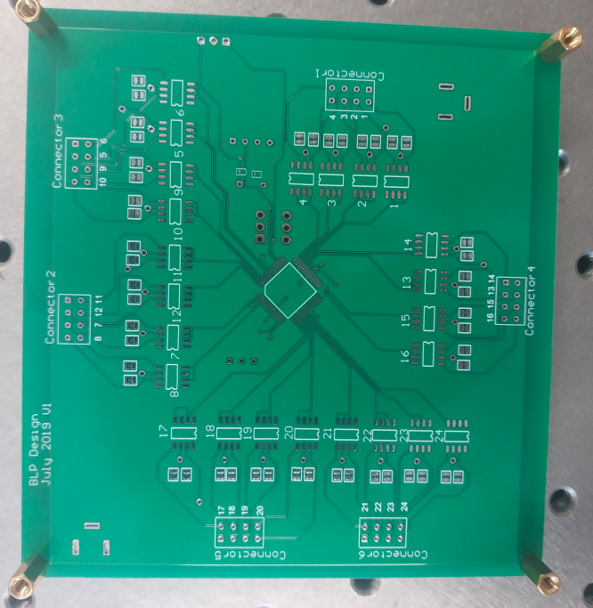
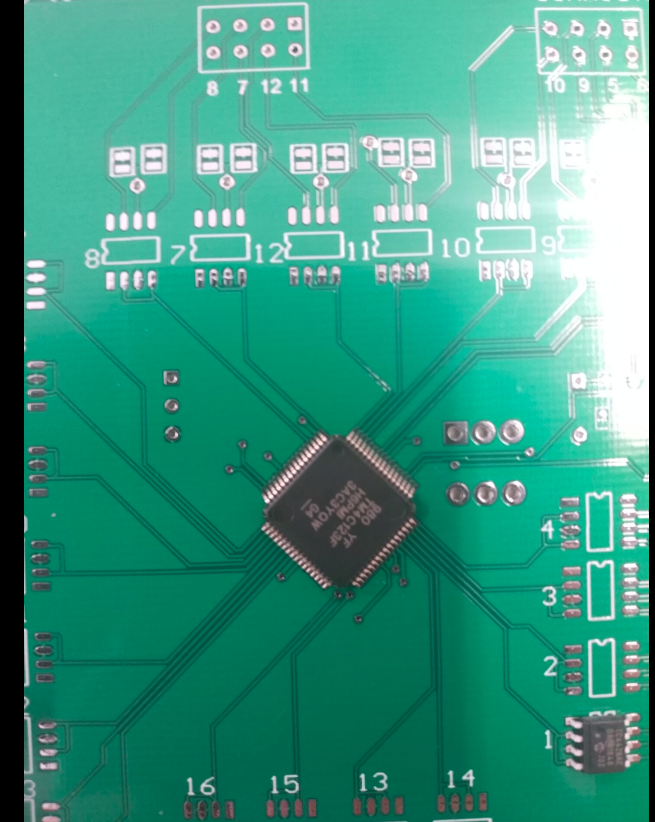
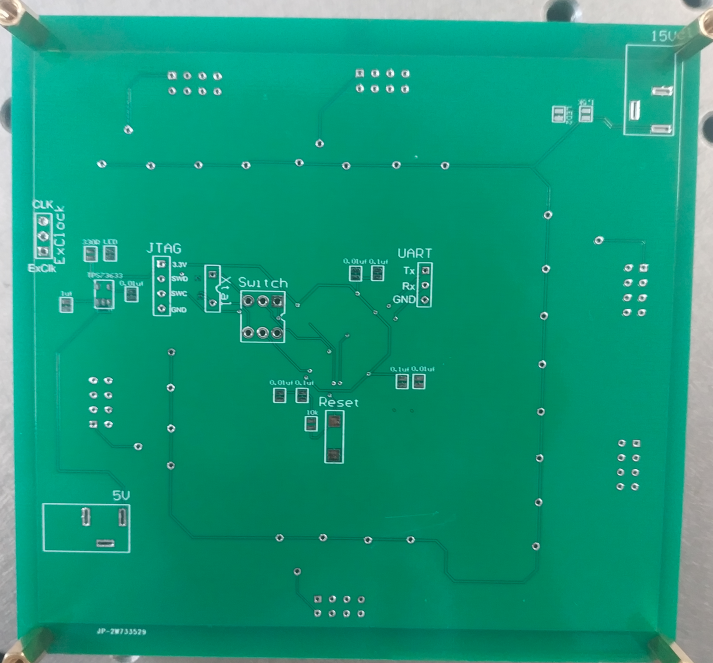
PCB
altium designer lecture
pcb for phased array
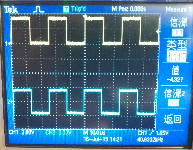
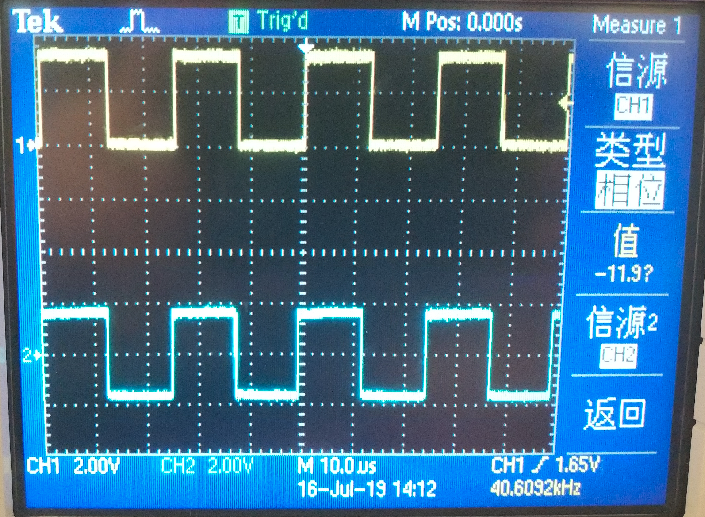
Oscilloscope
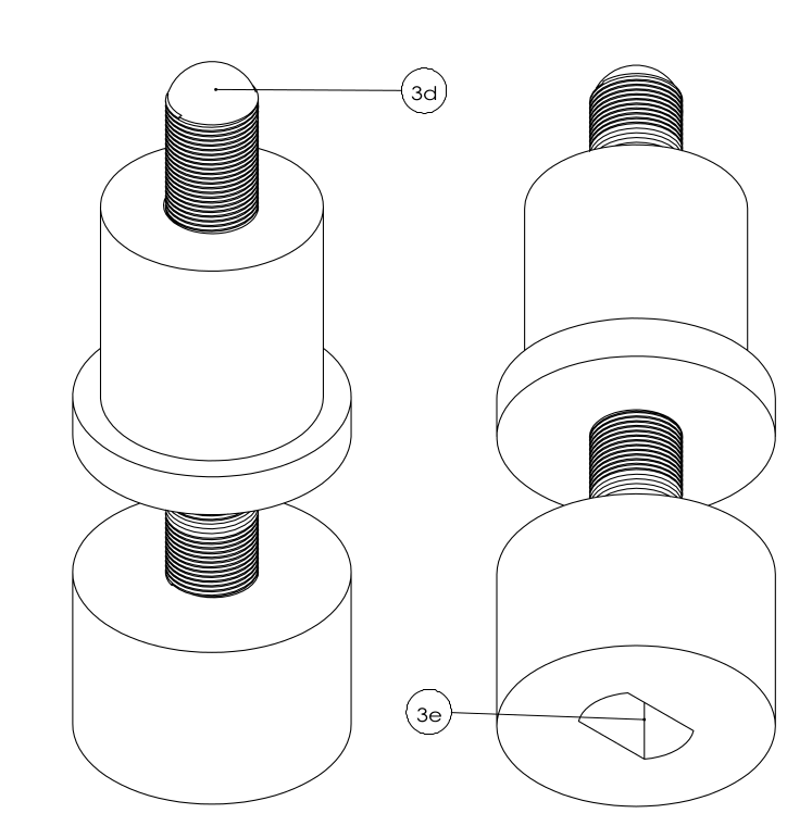
Other Drawings